 |
 |
INTRODUCTION
This is something a little bit different...
The Ray Dream Manual actually does provide the hint necessary to solve the central problem of this writeup. But it doesn't provide any concrete examples or procedures and you won't find the subject referenced in the index. So, the hint and its application would probably be obscure to all but the more experienced user or most diligent reader of the manual.
THE PROBLEM
While working on my B17 model, a number of comments suggested the addition of nose art--the often carnal illustrations which lonely, and very brave, young combat crew would paint onto the fuselage of their aircraft during WWII.
This seemed straightforward--simply apply the nose art as a paint shape over the existing fuselage shader.
The fuselage shader, itself, contains data in the color, highlight, shininess, bump and reflection channels.
For the nose art, I created a texture map in my favorite bitmap editor, Paint Shop Pro (PSP). It consisted of text and a figure on a white background, solely in the color channel.
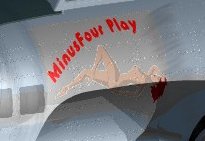
Despite having checked "white is Invisible," the first effort produced an oddly tinted border around the central figure and text. As can be seen in the first illustration (below), the background to the artwork may be transparent, but is obviously not invisible:
|
|
This was not a problem of the background being other than pure white--the RGB values were uniformly 255. [Go here if you want to know why it won't work.]
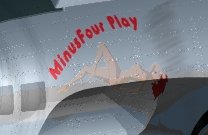
I then tried matching the original fuselage color and using that as the background color of the nose art texture map. This was fairly successful (see Illustration 2, above). But, Adrian van der Park pointed out that the figure and text appeared washed-out.
He was right, of course, and the explanation can be found on page 183 in the RD5 manual. The paint shape used only the color channel. The data in the underlying fuselage shader's remaining channels was being applied to the entire nose art paint shape--the highlight, shininess and reflection values of the fuselage shader were effecting the nose art's figure and text.
Attempts to reproduce the characteristics of the other channels within the paint shape were unsuccessful. Painting the nose art directly onto the fuselage was not an option; I was interested in finding a more elegant solution.
THE SOLUTION
What was needed was some way of simulating a mask--blocking the underlying highlight, shininess and reflection channels within the area of the figure and text, while allowing them to show within the background.
It was a short reference within the Ray Dream Handbook that led to the ultimate solution. Rick Greco's "Use Image Maps as Mask" on pp. 201-2, suggests that texture maps can be used within the Mix operator, but provides only a simple illustration and no elaboration. After looking at that illustration repeatedly over the course of a couple days, it dawned on me what was happening.
It was only after finishing the project that I stumbled across the critical information in the RD5 Manual which confirmed what was implied in that illustration: The white areas of a texture map used as a function within the Mix operator pick up the left subshader data, while the black areas of the map pick up the right subshader's data (RD5 Manual, p. 211).
Using this feature, it is possible to simulate the effects of a mask.
WHAT A MASK DOES
A texture map in the Mix operator let's you assign different values to different areas within one shader channel. Of course, you could use a grayscale map all by itself within a shader channel, but if you want the values to be anything more than all on or all off it would be nearly impossible to achieve precise values.
Let's say you have a decal (paint shape) with an irregularly shaped illustration that you want to apply to a surface with a high reflectivity value, such as a metal. Like a decal for the plastic models you used to play with, the paint shape is rectangular overall and you've got two areas within the paint shape: the illustration (the printed part), and the area outside the illustration (the plastic substrate on which it's printed).
The illustration needs a very low reflectivity, because you want it to look like a painted surface.
The area outside the illustration should have a higher reflectivity, because in order for it to disappear it will have to match the metal surface on which the decal is to be applied. You will, in addition, want this area outside the illustration to be transparent. (Think about it: Using the Transparency channel alone won't make it disappear because you still have to make the Reflectivity, Shininess and Highlight of both the metal and the unpainted part of the decal match. To illustrate: Glass is transparent, but the sun reflecting off it would make you notice a piece of it lying on a slab of concrete.)
The function of the map in the Mix operator is to allow you to specify two different areas of reflectivity within the one paint shape: one high to match the metal surface, one low to simulate a painted surface.
The next illustration shows the use of a map in the Mix operator within the Reflection channel, to produce the decal-on-metal under discussion.
Remember: The white areas of a texture map used as a function within the Mix operator pick up the left subshader data, while the black areas pick up the right.
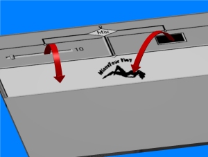 |
In this illustration, the white area of the map in the Function box causes the data in the left subshader--set to a value of 10 percent (which is the reflection value of the metal shader)--to be assigned to the unpainted areas of the decal. The black areas of the map are assigned the value from the right subshader. [Note: I used black in the right subshader just to experiment. I could just as easily have used a value slider set to zero. RDS interprets black as zero in this function].
The result is that the illustration has no reflectivity, and the unpainted part will exactly match the underlying metal surface. |
 |
The result, when combined with appropriate maps within the Highlight, Shininess and Transparency channels, and the illustration itself in the Color channel, is a decal that merges perfectly with the object to which it is applied. |
The easiest way to explain the procedure is by example:
PROCEDURE
NOTE: The following Steps 1 through 41 produce a rendering with a washed-out paint shape image. This section is included to demonstrate the problem and provide instruction in basic techniques to new users. For more experienced users, I recommend reviewing Steps 20 through 28, and then beginning the procedure at Step 42.
Create the Color and Mask Texture Maps
You'll need two maps. You can either copy the following two simple illustrations, or create maps of your own. If you want to copy these, right-click and Save As...*.bmp files (These are .gif files).
If you're creating your own maps, make one color and the other white and black. You can use any color as the background, but white is usually efficient. In your bitmap editor, create the mask from the color map, using whatever means is most appropriate. I used the Create Mask function within PSP, and then went back and saved the resulting "*.msk" as a .bmp file, but you could just as easily select the color portion and use a paint bucket tool to fill it with black.
 |
 |
Create the Object to be Shaded
We'll need a rectangular object to shade. If you know how to create a Free Form object in RD5, you can skip to Step 12, and we'll continue in the Perspective Window.
There's a trick to loading shader data into operator functions, which we'll be doing in a minute. In the Handbook, Richard Bucci wrote a section titled "Use the Browser to Copy Channels," p. 198. The following three steps use his suggestion:
Your screen should now appear something like this:
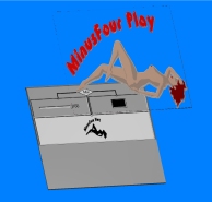
The rendered image should appear something like the following illustration--the paint shape shows some color, but is washed-out.
Now, we're going to use the maps we created to make the colored areas of the paint shape more vivid.
Set the Lighting
Apply the Base Shader
Record the Surface Settings
Empty the Shader Channels
Load and Save the Mask
Load the Color Texture Map
Apply the Paint Shape
Render the First Picture
Load the Maps into the Shader Channels
Your screen should look something like this:
We've taken care of the Highlight channel. Now, we're going to load the mask into the shininess and reflection channels. This goes much quicker:
Delete the Washed-Out Paint Shape
Before applying our revised shader, we need to get rid of that previously-applied washed-out paint shape:
Apply the Masked Paint Shape
Now we apply the revised, masked paint shape. The procedure is exactly the same as Steps 29-31.
When you've applied the new paint shape, render the image as before (Steps 34-41).
Compare this picture to the render made with the original map. You'll see how much more vivid the artwork is, and that the surface characteristics of the chrome shader are reproduced in the unpainted portions of the paint shape.
By using a map with the Mix operator, we have given the white area of the map values that match the original chrome shader, while the black area (the part that represents the art) has no such data assigned.
All constructive comments, suggestions, and corrections are welcomed.
All contents copyright 1999-2000 bilagaana. All rights reserved. Except as noted, the images may not be copied in any form without the permission of the author. Digitally watermarked.